 Triumph Street Triple S - Service manual > Electrical Connectors
Before beginning any diagnosis, the following connector related information should be noted:
Note:
- A major cause of hidden electrical faults can be traced to faulty electrical connectors. For example:
- Dirty/corroded terminals.
- Damp terminals.
- Broken or bent cable pins within multi-plugs.
For example, the electronic control module (ECM) relies on the supply of accurate information to enable it to plan the correct fueling and ignition timing. One dirty terminal will cause an excessive voltage drop resulting in an incorrect signal to the ECM.
If, when carrying out fault diagnosis, a fault appears to clear by simply disconnecting and reconnecting an electrical plug, examine each disconnected plug for the following.
Before Disconnection:
- If testing with a voltmeter, the voltage across a connector should be virtually battery volts (unless a resistor is fitted in the circuit). If there is a noticeable change, suspect faulty/dirty connections.
When Disconnecting a Connector:
- Check for a security device that must be released before the connector can be separated. E.G. barb, hook and eye etc.
When Inspecting a Connector:
- Check that the individual pins have not been bent.
- Check for dampness/dirt/corrosion.
- Check cables for security.
- Check cable pin joints for damage.
When Connecting a Connector:
- Ensure there is no dirt around the connector/seal.
- Push together squarely to ensure terminals are not bent or incorrectly located.
- Push the two halves together positively.
Disconnection of ECM connectors
Note:
- Two different coloured and shaped connectors are used in the
ECM, which ensures correct connection is always made.
The connectors on the ECM are coloured black and grey, and correspond with identical coloured connectors on the main harness.
Caution: When disconnecting a connector, never pull directly on the wires as this may result in cable and connector damage.
Caution: Never disconnect the ECM when the ignition switch is in the 'ON' position as this may cause multiple fault codes to be logged in the ECM memory.
Always disconnect an ECM after disconnecting the battery negative (black) lead first.
1. Turn the ignition to the 'OFF' position and wait at least 1 minute for the ECM to complete its power down sequence.
2. Press down on the locking device and gently pull back on the connector to release it from the ECM.
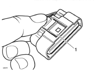
- Locking device
Note:
- The ECM is located beneath the fuel tank, on the upper section of the airbox.
Reconnection of ECM connectors
Note:
- Two different coloured and shaped connectors are used in the
ECM, which ensures correct connection is always made.
The connectors on the ECM are coloured black and grey, and correspond with identical coloured connectors on the main harness.
Caution: Damage to the connector pins may result if an attempt to fit the connectors incorrectly is made.
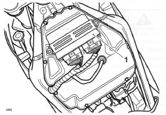
- ECM (Daytona 675 shown, Street Triple and Street Triple R similar)
1. Fit the first connector into its socket and, whilst holding the connector in place, insert it fully into the ECM until the locking device retains it.
2. Repeat the above for the second connector.
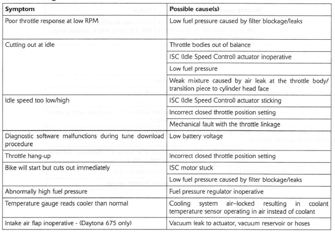
Further Diagnosis
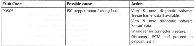
The tables that follow will, if used correctly, help to pinpoint a fault in the system once a diagnostic trouble code has been stored.
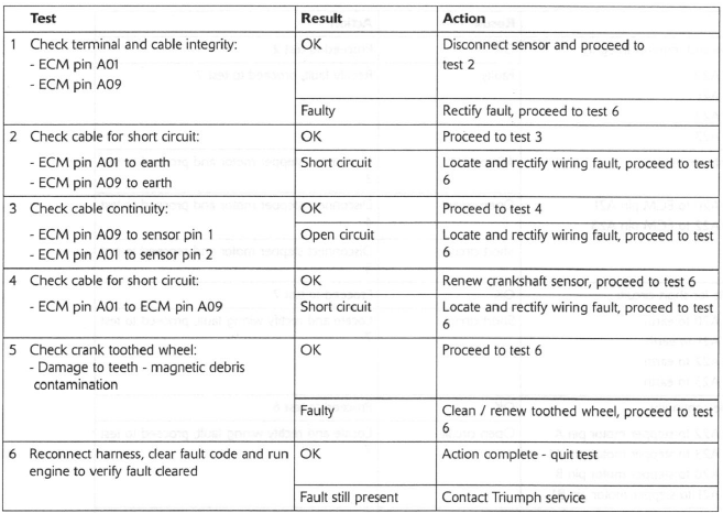
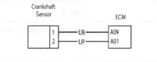
Crankshaft Sensor
Pinpoint Tests
Circuit Diagram
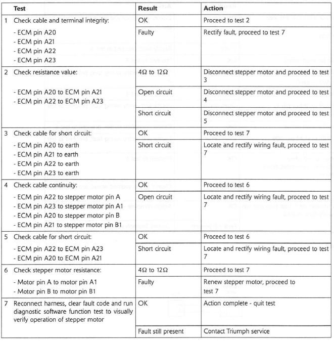
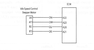
Idle Speed Control
Pinpoint Tests
Circuit Diagram
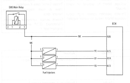
Fuel Injectors
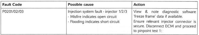
Pinpoint Tests
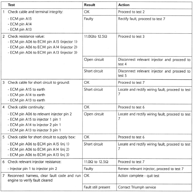
Circuit Diagram
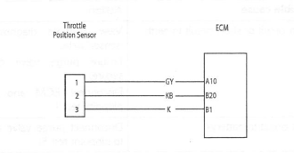
Throttle Position Sensor
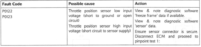
Pinpoint Tests
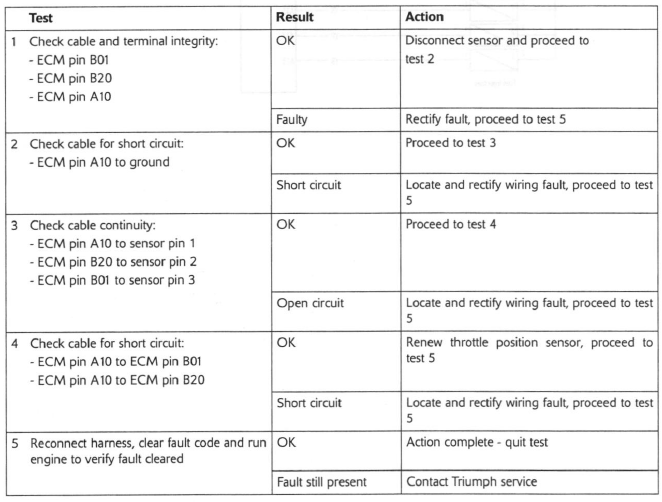
Circuit Diagram
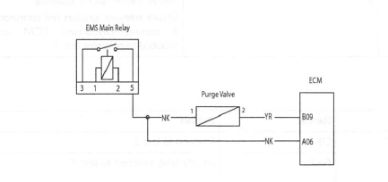
Purge Valve
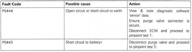
Pinpoint Tests
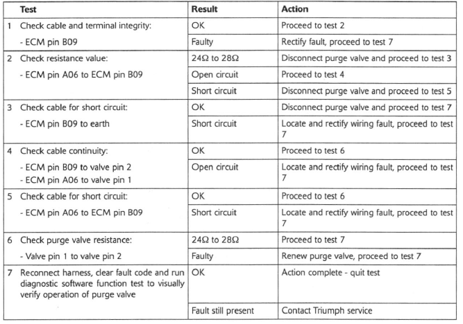
Circuit Diagram
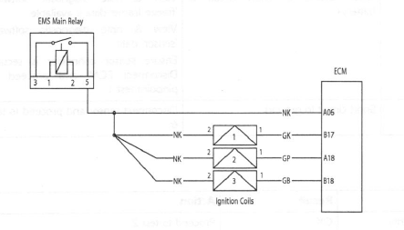
Ignition Coils
Pinpoint Tests
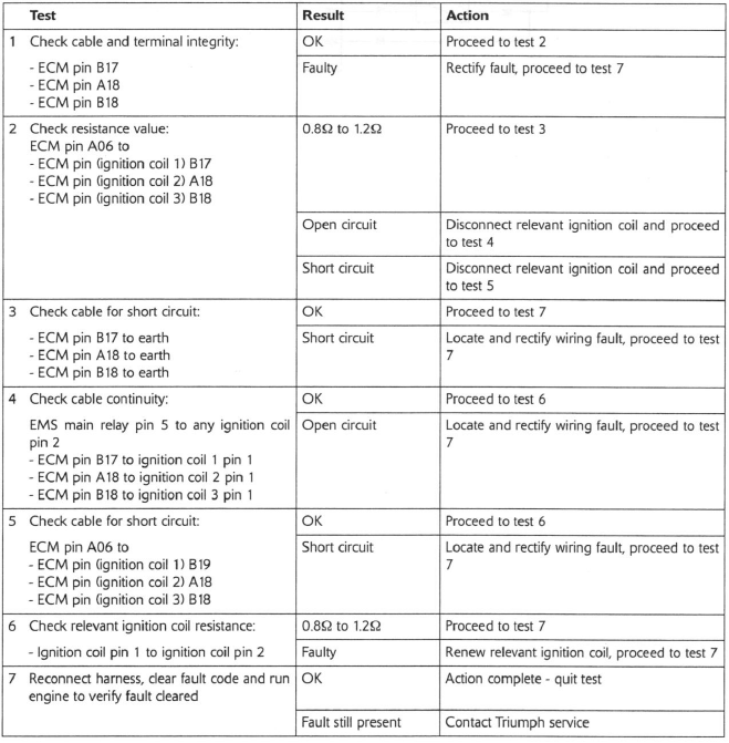
Circuit Diagram
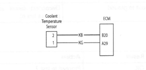
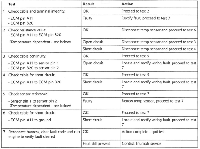
Coolant Temperature Sensor
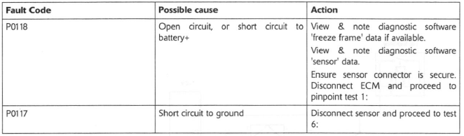
Pinpoint Tests
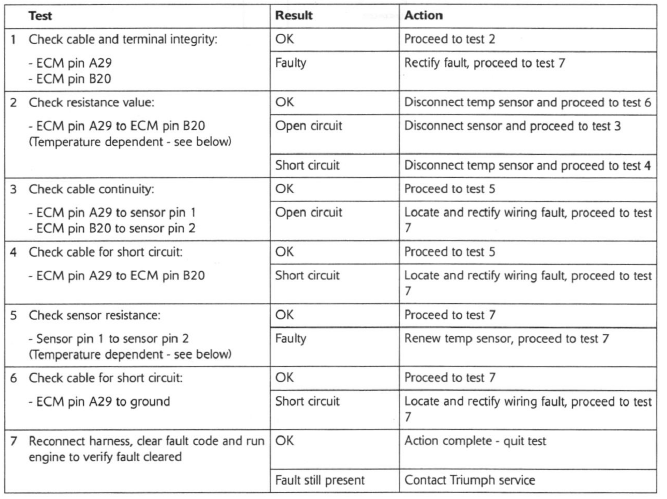
Circuit Diagram
Resistance data under typical conditions:
Warm engine: 200 to 400Ω
Cold engine:
20ºC ambient 2.35 to 2.65KΩ
-10ºC ambient 8.50 to 10.25KΩ
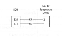
Intake Air Temperature Sensor
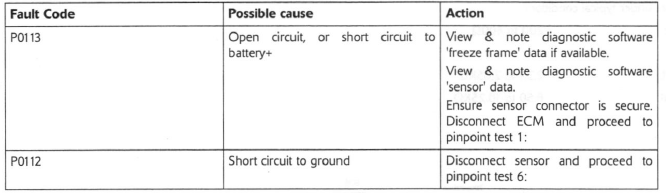
Pinpoint Tests
Circuit Diagram
If engine is warm, remove sensor and allow time to cool to ambient prior to test.
Resistance data:
Ambient temp Resistance value
80ºC 200 to 400Ω
20ºC 2.35 to 2.65KΩ
-10ºC 8.50 to 10.25KΩ
System Voltage
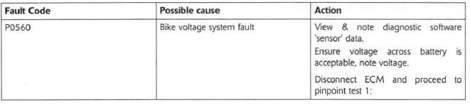
Pinpoint Tests
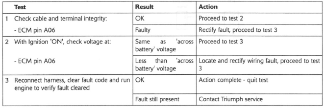
Circuit Diagram
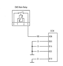
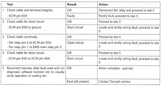
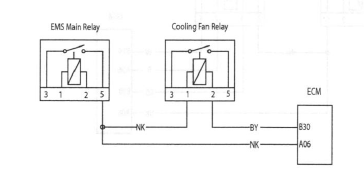
Cooling Fan Relay
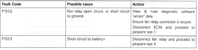
Pinpoint Tests
Circuit Diagram
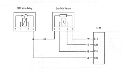
Lambda Sensor
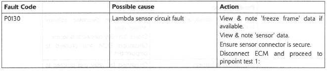
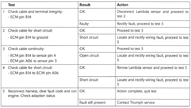
Pinpoint Tests
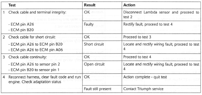
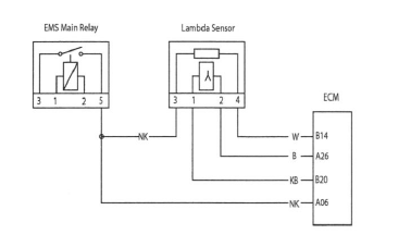
Circuit Diagram
Lambda Sensor Heater
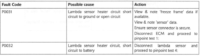
Pinpoint Tests
Circuit Diagram
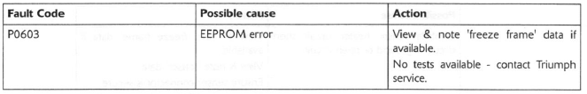
EEPROM Error
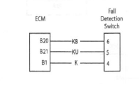
Fall Detection Switch
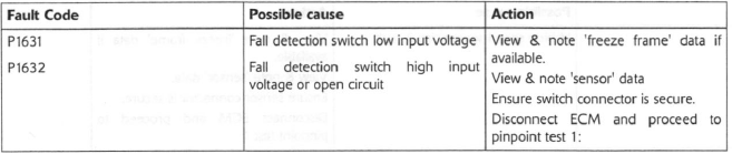
Pinpoint Tests

Circuit Diagram
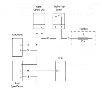
Vehicle Speed Sensor
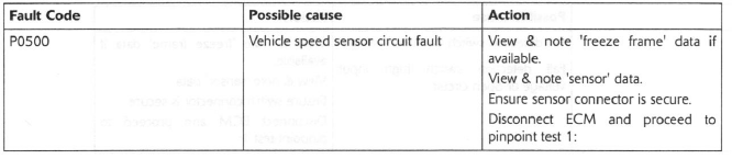
Pinpoint Tests
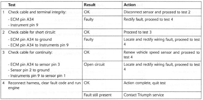
Circuit Diagram
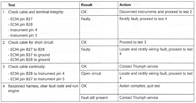
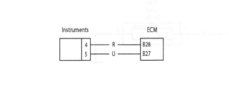
Instrument Communication (CAN)
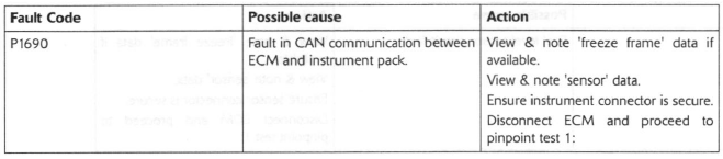
Pinpoint Tests
Circuit Diagram
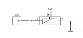
Fuel Level Sensor
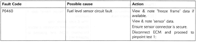
Pinpoint Tests
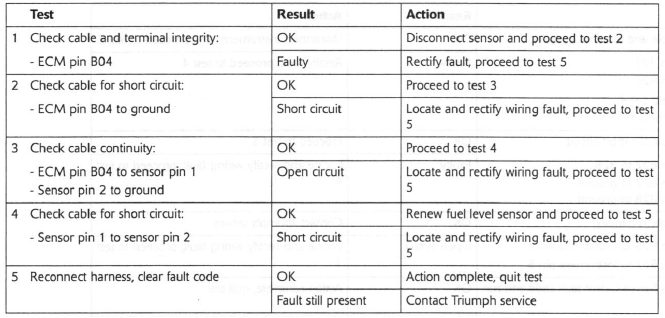
Circuit Diagram
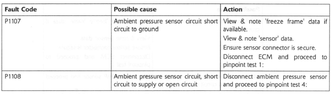
Ambient (Barometric) Pressure Sensor
Pinpoint Tests
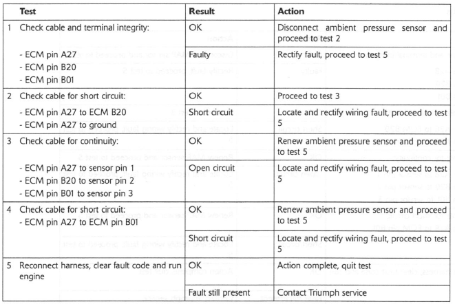
Circuit Diagram

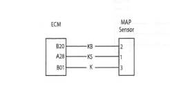
Manifold Absolute Pressure (Map) Sensor
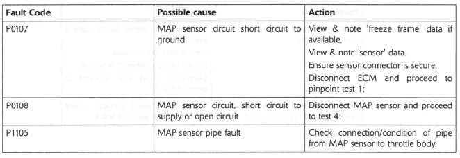
Pinpoint Tests
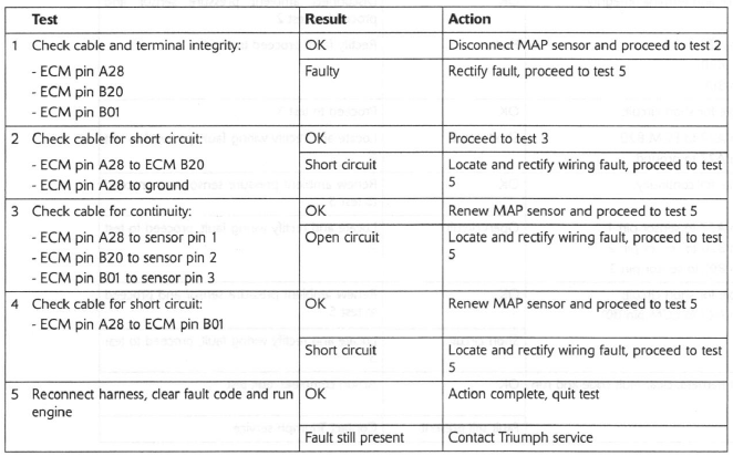
Circuit Diagram
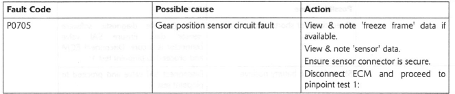
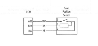
Gear Position Sensor
Pinpoint Tests

Circuit Diagram
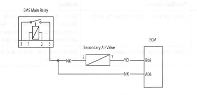
Secondary Air Injection Valve
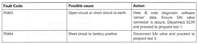
Pinpoint Tests
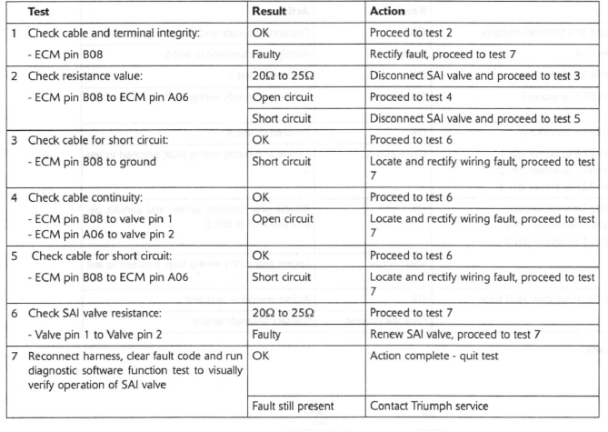
Circuit Diagram
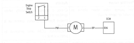
Fuel Pump - up to VIN 300525 - without Fuel Pump Relay
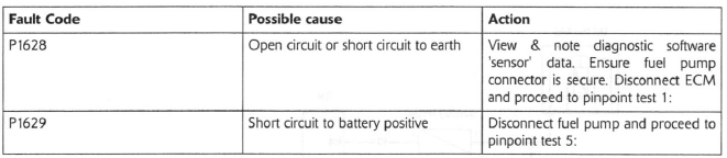
Pinpoint Tests
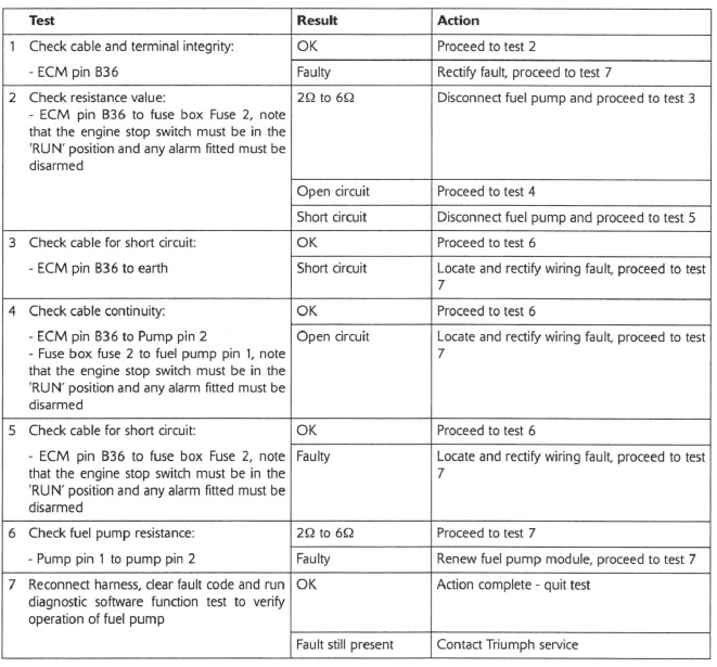
Circuit Diagram
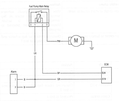
Fuel Pump - from VIN 300526 - with Fuel Pump Relay
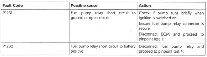
Pinpoint Tests
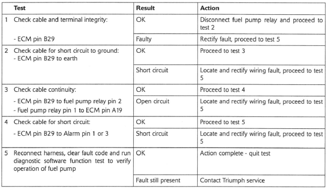
Circuit Diagram
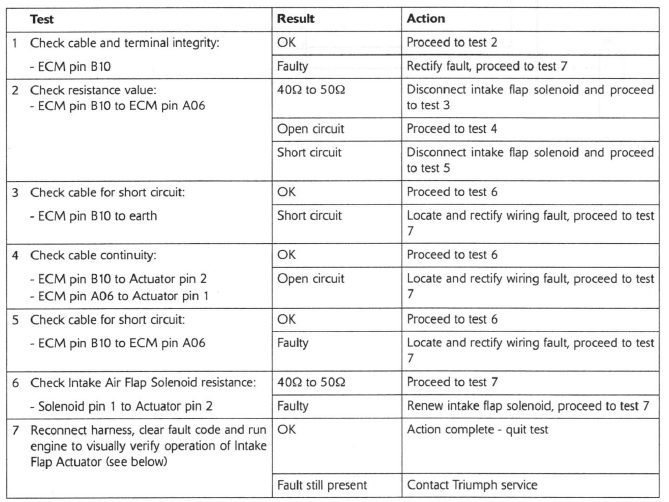
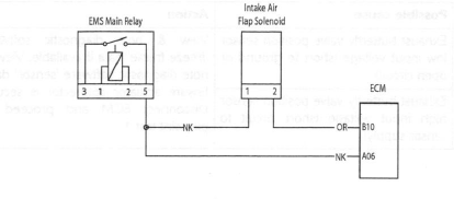
Intake Air Flap Solenoid - Daytona 675 only
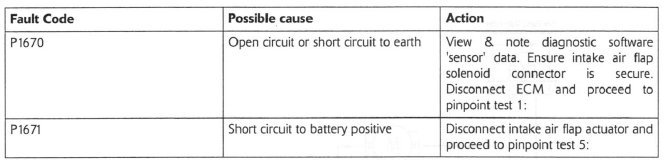
Pinpoint Tests
Note:
- To verify the correct operation of the air intake flap, start the engine and briefly raise the engine speed above 4500 rpm. The flap should be seen to open as the engine speed rises and close again as the engine speed falls.
Circuit Diagram
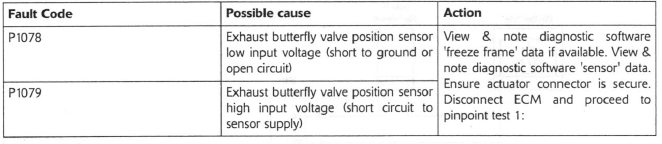
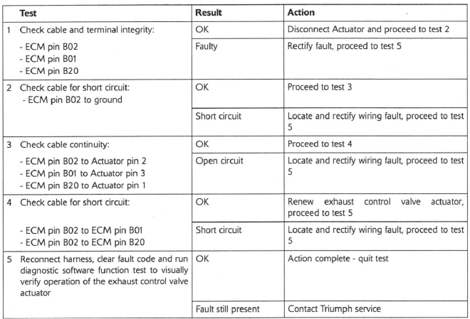
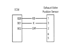
Exhaust Butterfly Valve (EXBV) Position Sensor - Daytona 675 only
Pinpoint Tests
Circuit Diagram
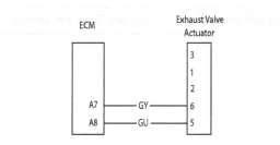
Exhaust Butterfly Valve (EXBV) Motor - Daytona 675 only
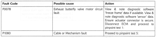
Pinpoint Tests
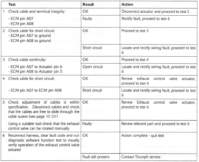
Circuit Diagram
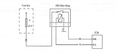
EMS Main Relay Circuit
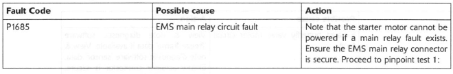
Pinpoint Tests
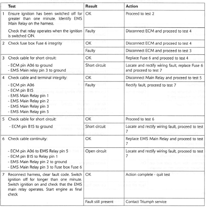
Circuit Diagram
EMS Ignition Voltage Input Circuit
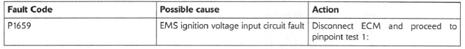
Pinpoint Tests
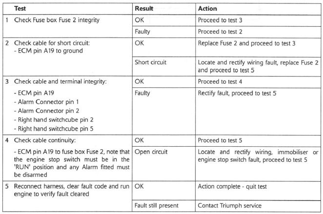
Circuit Diagram
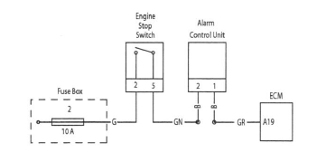
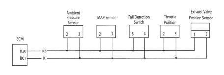
5 Volt Sensor Supply Circuit
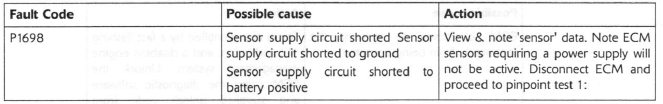
Pinpoint Tests
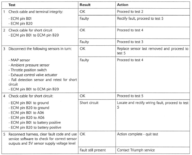
Circuit Diagram
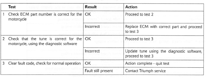
Tune Lock
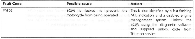
ECM or Tune ID Incorrect
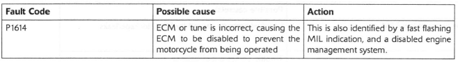
Pinpoint Tests
Fault Finding - Non Electrical
See also:
 Triumph Street Triple S - Service manual > System Diagnostics
The engine management system has an on-board diagnostics feature which allows service technicians to retrieve stored data from the ECM using the Triumph diagnostic software. Full details of the Triumph diagnostic software operation and how to interpret the results are given in the Triumph Diagnostic Tool User Guide.
Triumph Street Triple S - Service manual > Fuel Tank
Removal Warning: Observe the warning advice given in the general information section on the safe handling of fuel and fuel containers. A fire, causing personal injury and damage to property, could result from spilled fuel or fuel not handled or stored correctly.
 Benelli Imperiale 400
 BMW F900XR
 Honda CB500X
 KTM 390 Adventure
 Triumph Street Triple S
 Yamaha MT-03
 Kawasaki Z400
 Triumph Street Triple S
 Yamaha MT-03