 Kawasaki Z400 - Service manual > Idle Speed Control Valve Actuator (Service Code 1 C) (DTC P0508, P0509,
PO518)
Kawasaki Z400 - Service manual > Idle Speed Control Valve Actuator (Service Code 1 C) (DTC P0508, P0509,
PO518)
Idle Speed Control Valve Actuator Removal
- Remove: Throttle Body Assy (see Throttle Body Assy Removal)
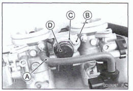
- Disconnect the intake air pressure hose [A].
- Remove: Idle Speed Control Valve Actuator Screw [B] Prate [C] Idle Speed Control Valve Actuator [D] Spring
Idle Speed Control Valve Actuator Installation
- Measure the plunger position.
Plunger Position 44 ~ 50 mm (1.7~ 2.0 In.) [A]
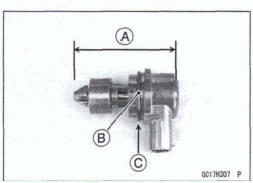
*If the plunger position is not within the specified range, replace the idle speed control valve actuator.
- Replace the O-ring [B] with a new one.
- Fit the O-ring into contact with the step [C].
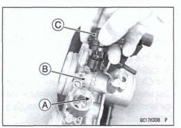
- Apply a small amount of engine oil to the throttle body [A].
- Install the spring [B] to the idle speed control valve actuator [C] as shown.
- Install the idle speed control valve actuator straight to the throttle body
- Turn the ignition switch on.
- Turn the ignition switch off, and wait for 2 or 3 seconds
- Inspect the idle speed (see Idle Speed Inspection in the Periodic Maintenance chapter).
Idle Speed Control Valve Actuator Resistance inspection
- Turn the ignition switch off.
- Remove the air cleaner housing (see Air Cleaner Housing Removal).
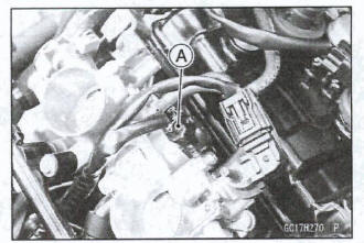
- Disconnect the idle speed control valve actuator connector [A].
- Connect a digital meter to the idle speed control valve actuator connector [A].
- Measure the idle speed control valve actuator resistance.
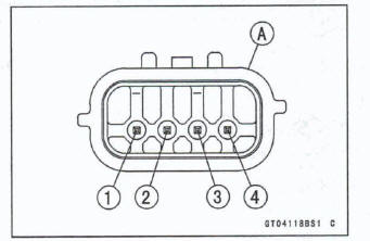
ldle Speed Control Valve Actuator Resistance
Connections: G/R lead [I] ←→ G/BK lead [2]
G/O lead [3] ←→ G/Y lead [4]
Standard: About 20 
*If the reading is out of the standard, replace the idle speed control valve actuator.
*If the reading is within the standard, check the input voltage (see Idle Speed Control Valve Actuator input Voltage Inspection).
Idle Speed Control Valve Actuator Input Voltage Inspection
NOTE
Be sum the battery is fully charged.
- Turn the ignition switch off.
- Remove: Air Cleaner Housing (see Air Cleaner Housing Removal,
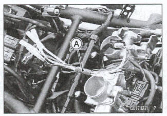
- Disconnect the idle speed control valve actuator connector
and connect a suitable measuring leads [A] between
these connectors as shown.
Main Harness [B] Idle Speed Control Valve Actuator [C]
- Connect the peak voltage adapter [D] and a digital meter [E] to the measuring adapter leads.
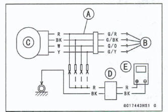
Idle Speed Control Valve Actuator Input Voltage Connections to Adapter:
(I) Digital Meter (+) → R (actuator G/R) lead
Digital Meter (-) → BK (actuator G/BK) lead
(11) Digital Meter (+) → W (actuator G/O) lead
Digital Meter (-) → Y (actuator G/Y) lead
- Measure the actuator input voltage with the engine stopped and with the connector joined.
- Turn the ignition switch on.
Input Voltage Standard: About DC I1 - 13 V and then 0.5 V or About DC 11 -13V
- Turn the ignition switch off.
*If the reading is out of the specification, remove the ECU and check the wiring for continuity between main harness connectors.
- Disconnect the ECU and actuator connectors.

Wiring Continuity Inspection
ECU Connector [A] ←→
Idle Speed Control Valve Actuator Connector [B]
ECU terminal 1 [C] ←→ Actuator Terminal [D]
ECU terminal 2 [E] ←→Actuator Terminal [F]
ECU terminal 18 [G]←→Actuator Terminal [H]
ECU terminal 19 [I] ←→Actuator Terminal [J]
*If the wiring is good, check the ECU for its ground and power supply (see ECU Power Supply Inspection).
*If the ground and power supply are good, replace the ECU (see ECU Removal/Installation).
Idle Speed Control Valve Actuator Circuit
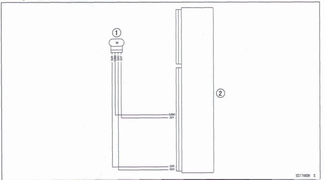
- Idle Speed Control Valve Actuator
- ECU
See also:
 Kawasaki Z400 - Service manual > Stick Coils #1, #2 (Service Code 51, 52) (DTC P0351, P0352)
Inspect the eligible stick coil according to the following service code or DTC. Service Code 51/DTC PO351→ Stick Coil #1 Service Code 52/DTC PO352 →P Stick Coil #2
Kawasaki Z400 - Service manual > Purge Valve (Service Code 3A) (DTC P0443) (Equipped Models)
Purge Valve Removal/Installation Remove: Left Middle Fairing (see Middle Fairing Removal in the Frame chapter) Disconnect the purge valve connector [A] Remove
 Benelli Imperiale 400
 BMW F900XR
 Honda CB500X
 KTM 390 Adventure
 Triumph Street Triple S
 Yamaha MT-03
 Kawasaki Z400
 Triumph Street Triple S
 Yamaha MT-03